ERW Pipe Making Process: From Steel Coil to Finished Tube
ERW pipe is cold-formed from steel strip and HF-welded without filler metal. This guide follows each tube mill stage, from coil to finished tube.
Read article06 · TUBE FORMING & SIZING
The forming and sizing mill rolls strip into a tube blank, welds it by HF induction, then sizes and straightens it into round, square or rectangular tube.
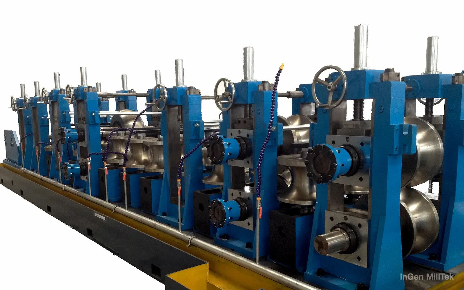
 Illustrative render Its place in the line
Strip entering the mill is rolled step by step into an open tube blank by the horizontal and vertical rollers of the forming section. The seam is heated to welding temperature by high-frequency induction and pressed together by the squeeze rollers. The outside weld bead is scarfed off, the tube is cooled, the sizing section rolls it to its final dimensions and a rough straightener finishes it. Forming, welding, cooling, sizing and the drive make up a complete mill.
The mill uses roll forming and can produce different sizes with the appropriate rollers within the confirmed configuration and operating range. Define round-tube and square or rectangular arrangements separately. Round-to-square forming and direct square forming are different process routes requiring the corresponding mill and tooling configuration. The stands are gantry-type with side roller change, driven through gearboxes and universal shafts.
The model number is the nominal tube diameter. The actual diameter, wall thickness and speed range of each model is in the table below. Diameter, wall thickness and speed cannot be combined arbitrarily: confirm the available speed for each product against its material, welding, cooling and cutting conditions rather than inferring it from one dimension. For thin-wall products slightly beyond a model's range we can discuss a widened mill, which uses the stands of a smaller model to make larger-diameter thin-wall tube.
Start the selection with the product: tube shape, size and wall thickness range, material, end use and tolerances, target speed and how often sizes change. From these we define the model, the roller tooling and the line composition.
Define the roller-tooling plan around actual product combinations, not only the size range associated with the mill model. Regular products, changeover frequency and the selected forming route affect tooling and production planning. Specify round-tube and square/rectangular-tube arrangements separately; different forming methods should not be assumed to use the same tooling or configuration.
Technical confirmation should cover coordination among HF welding, weld treatment, cooling and sizing, along with interfaces to entry equipment, cutting and run-out. Use agreed materials and tube specifications for acceptance, recording dimensions, weld quality and other agreed requirements against the operating conditions.
Used in these lines Tube mill lines · 12 models, complete lines
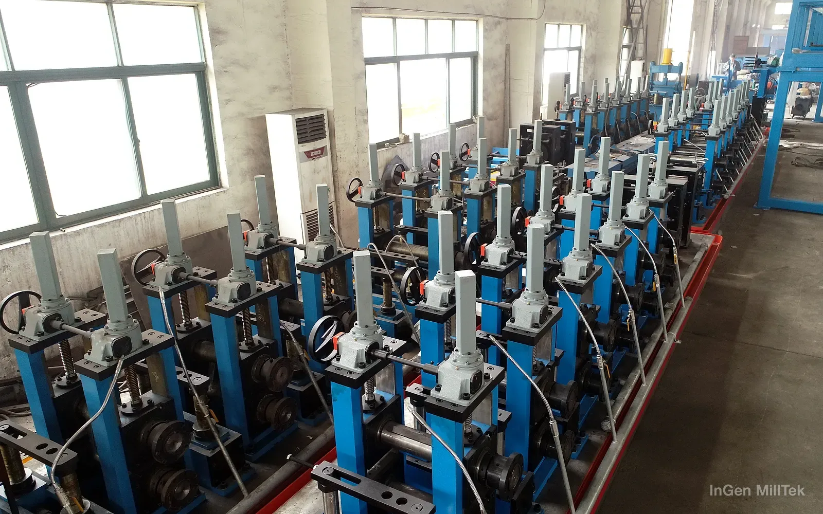
Actual specifications depend on the material and final equipment configuration.
| Model | Round tube OD mm | Wall mm | Square tube mm | Wall mm | Rectangular tube mm | Wall mm | Line speed m/min |
|---|---|---|---|---|---|---|---|
| YJ-20 | Φ10–25.4 | 0.4–1.5 | 8×8–20×20 | 0.4–1.0 | 10×6–25×15 | 0.4–1.0 | 0–100 |
| YJ-32 | Φ12.7–38.1 | 0.4–2.0 | 10×10–30×30 | 0.4–1.5 | 12×8–40×20 | 0.4–1.5 | 0–120 |
| YJ-50 | Φ19.1–63.5 | 0.6–3.0 | 15×15–50×50 | 0.6–2.5 | 20×10–60×40 | 0.6–2.5 | 0–100 |
| YJ-76 | Φ38.1–89 | 0.8–3.5 | 30×30–70×70 | 0.8–3.0 | 40×20–80×60 | 0.8–3.0 | 0–80 |
| YJ-89 | Φ50–102 | 1.0–4.0 | 40×40–80×80 | 1.0–3.5 | 50×30–90×70 | 1.0–3.5 | 0–70 |
| YJ-102 | Φ50–114 | 1.2–4.5 | 40×40–90×90 | 1.2–4.0 | 50×30–100×80 | 1.2–4.0 | 0–70 |
| YJ-114 | Φ63.5–127 | 1.5–5.0 | 50×50–100×100 | 1.5–4.2 | 60×40–120×80 | 1.5–4.2 | 0–60 |
| YJ-127 | Φ63.5–140 | 1.5–5.0 | 50×50–110×110 | 1.5–4.5 | 60×40–130×90 | 1.5–4.5 | 0–60 |
| YJ-165 | Φ76–165 | 1.5–6.0 | 60×60–130×130 | 1.5–5.0 | 70×50–150×110 | 1.5–5.0 | 0–50 |
| YJ-219 | Φ89–219 | 2.0–8.0 | 70×70–170×170 | 2.0–7.0 | 80×60–190×150 | 2.0–7.0 | 0–50 |
| YJ-254 | Φ114–254 | 3.0–9.0 | 90×90–200×200 | 3.0–7.5 | 100×80–250×150 | 3.0–7.5 | 0–40 |
| YJ-273 | Φ140–273 | 4.0–10.0 | 110×110–215×215 | 4.0–8.5 | 130×90–250×180 | 4.0–8.5 | 0–30 |
Square and rectangular sizes are side-length ranges. Size, wall thickness and speed are not independent combinations; actual capability depends on the material and final configuration.
Further standard and custom models are available on request.
Source: company product catalogue (April 2025 edition), page 12.
Use these points to prepare the equipment discussion. Specifications and configuration depend on the project.
We discuss the suitable model and configuration for your product and plant. Every line is configured per project, and pricing follows the configuration.